


|
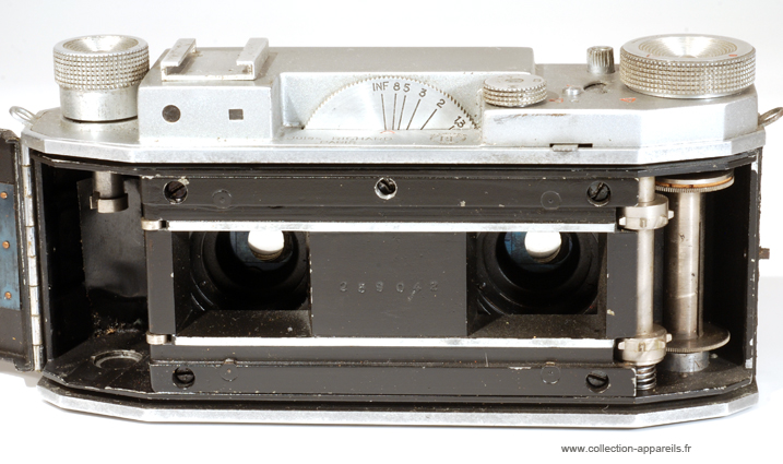
Richard Jules Verascope 40 |
Manufactured or assembled in France from 1939 to 1958.
Index of rarity in France: Rare (among non-specialized garage sales)
Inventory number: 6452
See the complete technical specifications
Chronology of cameras Richard Jules
Félix Richard was born in Lyon in 1809 from an old family of silk producers. He became a precision instrument maker and optician on Quai Saint-Antoine. In 1855, he moved to Paris and led a significant industry manufacturing barometers and pressure gauges. He served as a member of the government in 1870 and as the mayor of the 19th arrondissement. However, he neglected his business, and upon his death on July 14, 1876, his company was burdened with debt.
Félix-Max and Jules took over the company under the name Richard Frères (hence the acronym "RF"). In 1888, their brother Georges joined them until 1891. Jules then bought out his brothers' shares but retained the company name. Jules passed away at the age of 82 on June 18, 1930, holding the title of Commander of the Legion d'Honneur, a well-deserved recognition for his industrial activities, involvement in stereoscopy, and the establishment of an apprenticeship school.
As a passionate photographer, Jules Richard constructed a revolutionary stereoscopic camera in 1893. He was the first to understand the necessity of having lenses spaced apart to recreate a perspective that "renders the image in true size with depth." Another innovation was his adoption of a tiny format for the time, 4 cm by 4 cm, while the average amateur regularly used 13 cm by 18 cm.
Advocating for the small format, which was commercially successful, Jules nonetheless offered a series of Homéoscope cameras (1895-1904) to satisfy his friends and provide them with a high-quality camera in their preferred format, available in 8 cm by 9 cm and 6 cm by 6.5 cm, with or without a magazine, but in very limited quantities. Despite its initial simplicity, the Vérascope was an expensive camera due to its precision craftsmanship. To popularize stereoscopy in his favored format, Jules Richard introduced the Glyphoscope in 1905. Interestingly, three models were offered with the same technical specifications. In 1908, a special model for film packs was released. In 1927, a 6 cm by 13 cm model was introduced, which would have slow speeds by 1930. The façade of the Glyphoscope was detachable, allowing it to be used as a viewer.
In 1905, to satisfy the members of the Stéréo-Club de France, he offered a Vérascope in a 7 cm by 13 cm format, the maximum allowed by the interocular distance. Price and competition would reduce the sales of these models, but various increasingly sophisticated variants were still offered. A simplified model was presented in 1923, and in 1928, the Vérascope adopted the 6 cm by 13 cm format. In 1913, Jules patented the Homéos, the first stereoscopic camera using 35 mm cine film, but it was not available for purchase until 1920. He reaffirmed his interest in the small format, with the resulting images measuring 18 mm by 24 mm.
In 1931, the Stéréa 6 cm by 13 cm was offered in two versions, varnished wood or metal, but with the same technical specifications. Positioned between the Vérascope and the Glyphoscope, they entered a crowded market. In 1939, the Vérascope 40 was patented, using 35 mm film with a new image format, 24 mm by 30 mm, which would remain distinctly French. This modern camera was distributed in the USA by the Bush company.
D'après son N° 259042, cet appareil est d'avril (04) 1942 (2). Et c'est le 259ème de la série.
Il est marqué dans le cuir "Vérascope 40", il a le petit levier d'armement en façade, le disque pour la mise au point est plat, mais il dispose d'une prise de synchro-flash. Celle-ci n'est certainement pas d'origine, mais la qualité de l'usinage me fait penser qu'elle a été rajoutée aux usines Richard Frères.
L'autre particularité est l'équipement optique avec deux Saphir de Boyer. (237232 et 237233). Proposés un peu moins chers que les Flor de Berthiot, ces objectifs ont été boudés par les acheteurs et sont (très) rares sur les Vérascope 40.

The Vérascope in Photo-Revue (1945) by J. Cousinet, Engineer at Etablissements Richard
FOREWORD
The Vérascope 40 and its reverse stereoscope are now well-known to amateur photographers, and the purpose of this article is not to describe them once again. However, precisely because photographers are in a position to assess and critique this equipment's performance today, it does not seem unnecessary, after hearing the prosecution's witnesses, to give the floor to the defense, i.e., the manufacturer, to allow them to justify the solutions they have adopted.
This is, therefore, a brief technical plea that we present to the readers of Photo-Revue with the aim of shedding light on the arguments that appeared to us to be the best for choosing one characteristic over another in the design of our camera.
We will examine the following points in this regard:
1. General Conditions of Use (Choice of 35mm film, use of strips, color use, etc.).
2. Format.
3. Focal Length.
4. Aperture.
5. Focusing Procedure - Rangefinder Coupling.
6. Mechanical Functions.
7. Exploitation of Images - Enlarger and Reverse Stereoscope.
1. General Conditions of Use
While the merit of the small format may be debated in monocular photography, the same does not apply to stereoscopy, where its superiority is evident. The main reason for this is that stereoscopic images must be viewed through a magnifying optic. The small format, therefore, introduces no new complications and brings all its advantages (compactness, extended depth of field, etc.). It is particularly suitable to use the standard 35-millimeter cine film in this context.
The recent availability of color emulsions in this format was another decisive argument. What was needed to make film stereoscopy practical? A fundamental question dominated the problem: to simplify to the maximum the tedious but inevitable "reversal," especially considering that color film, when used as is, no longer allowed for this operation during positive printing.
The first condition we imposed on ourselves was, therefore: no cutting, no reversal during printing, direct examination of the strips through a so-called "reversing" stereoscope. Thus, the fate of the Vérascope 40 was linked, from the outset, to that of its essential complement: the stereoscope.
2. Format
At first glance, one might be tempted to criticize the 24 x 30 format and compare it to either the square format, which is classic in stereoscopy, or the 24 x 36 format popularized by several high-quality foreign cameras. However, the choice of format in stereoscopy is not arbitrary due to the following dual obligation:
1. Maintain the average distance between the axes of two homologous images: 63 mm.
2. Not lose sensitive surface area.
Ultimately, these two conditions can be expressed as follows: the horizontal dimension of the image must be a multiple of 63 (within reasonable margins). There are few viable solutions:
- 63/2 leads to the format 31.5 x 24.
- 63/3 leads to the format 21 x 24.
It is unnecessary to emphasize that going below or beyond these two numbers would be absurd. Moreover, there is little room for hesitation between these two numbers, considering that the space separating two images must be taken from the dimension of either 31.5 or 21. Additionally, the same applies to the non-overlapping portions (which are lost for stereoscopy), potentially reducing the theoretical image size of 21 x 24 to a simple vertical strip.
 Therefore, it is evident that the first solution is the only acceptable one. It leads us to the 24 x 30 format while reserving a 1.5 interval. This format has the advantage of corresponding to a common paper size.
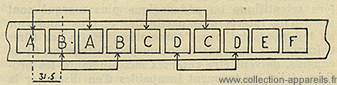
The arrangement of the images on the strip is also not overly complicated. Between two homologous views, only one foreign view is intercalated, which is unrelated to the considered stereoscopic pair. This arrangement provides the sequence of views as illustrated in diagram 1.
3. Focal Length
The choice of a 40 mm focal length provides a medium field of view angle and ensures normal coverage of the format. A longer focal length would have had significant consequences on the dimensions of the camera.
1. In terms of depth, this is evident because the camera is of the rigid type.
2. In terms of width, increasing the diameter of the lenses for the same aperture would result in an increase in the length and travel of the shutter blades.
4. Relative Aperture
In this case, the value of 3.5 cannot be defended as an optimum value, as it is always advantageous to have the widest aperture possible. However, it must be accepted as a limit for the reasons mentioned earlier, as the size and weight of the camera increase quite rapidly with the diameter of the lenses. For example, a lens with an aperture of 2.8 would have led to a camera that is 12 mm longer and approximately 150 grams heavier.
5. Focusing Procedure - Rangefinder Coupling
The focusing control mechanism is similar to that of the Vérascope Richard 45 x 107 and 6 x 13, and we won't dwell on it here. The novelty of the Vérascope 40 lies mainly in its rangefinder. This rangefinder has two interesting features: the mirror and the coupling method.
A. Glass (Figure 2).
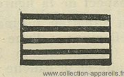 It is composed of a network of alternating horizontal stripes, with some being transparent and others reflective. The transparent stripes are made from untreated glass, while the reflective stripes are made by silvering portions of the glass in the same way as an ordinary mirror.
This type of glass offers two advantages: firstly, it doesn't have the fragility of glass created with thin cathodic deposits. Secondly, the "mixing" of the respective intensities of direct and reflected images is simple and precise because the ratio of these intensities is equal to the ratio of the widths of the transparent and reflective stripes.
From an optical perspective, the behavior of such glass is exactly the same as that of semi-transparent glass, provided that the eye is positioned at a distance much smaller than the minimum distance required for distinct vision. Under these conditions, the eye does not perceive the network but receives the rays that pass through it or are reflected by it, and in both cases, it essentially synthesizes the image.
B. - Rangefinder Coupling Mode (Figure 3).
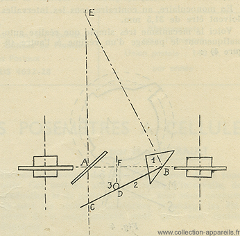 The particularity of the adopted system is to directly rely on a simple geometric relationship. The total reflection prism 1 is connected to a lever arm 2 that can rotate around the vertical axis passing through point B. This lever arm 2 consistently rests on a finger 3, which is part of the camera body. Conversely, the base of the rangefinder AB is connected to the lens mount.
During the movement of the lens mount for focusing the camera on an object E, for example, the prism undergoes a certain rotation. To ensure that the rangefinder is adjusted to object E, it is necessary for ray EB to reflect off prism 1 along the path BA. This is possible by giving the lever arm 2 an appropriate length. Indeed, the forward movement DF of the lenses is inversely proportional to the distance between object E and the anterior focal plane (Fundamental equation of lenses). Furthermore, in the right triangle EBC, the length AC is inversely proportional to the length AE (with the geometric mean being the height AB of the triangle).
Therefore, if we neglect the focal length of the lenses relative to their distance from the object, which is legitimate in a short focal length camera, the laws governing the movement of the lenses and the rangefinder are nearly identical except for a constant factor.
The advantage of this arrangement is to make the rangefinder adjustment simple and methodical, as it boils down to adjusting the length of the lever. For the same reason, the adjustment is obviously more precise than in cam-based devices where one relies on a more complex profile.
6. Mechanical Functions
We won't delve into the details of all the mechanical functions of the Vérascope 40, but we'll mention one feature specific to this camera, which is the mode change mechanism (stereo-monocular).
It seemed interesting, especially in a time when the prices of high-quality cameras are continually rising, to provide stereoscopic photographers with the ability to take monocular photographs without the need for another camera. What was needed to temporarily transform a stereoscopic camera into a monocular camera?
1. Close one of the lenses.
2. Change the film's metering mode.
The first condition did not pose a difficulty. To understand the second condition, let's refer to diagram 1. In stereo mode, we can see that the film advances in an alternating pattern of two intervals: one of 31.5 mm (for example, to go from image AA to image BB), and the other of 3 times 31.5 mm (to go from image BB to image CC), and so on. In monocular mode, on the other hand, all intervals must be 31.5 mm.
Here's the very simple mechanism that automatically switches between modes (Figure 4):
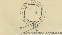 A plate 1 is driven by the film transport mechanism to make one complete revolution for every 4 x 31.5 mm of film transported. This plate has 4 teeth positioned at 90° from each other, with two of these teeth being taller than the other two.
Additionally, a stopper 2 is placed in the path of these teeth to halt the plate's movement. This stopper can occupy two positions. In position S, it only engages with the two taller teeth, and it is evident that in this case, the plate will alternately rotate by 1/4 turn and 3/4 turn. Consequently, the film will advance alternately by 31.5 mm and 3 times 31.5 mm. This corresponds to the stereoscopic mode.
On the other hand, if the stopper 2 is in position M, it engages with all the teeth, causing the plate to rotate by 1/4 turn each time. Therefore, the film advances by 31.5 mm in this case, which corresponds to the monocular mode. Stopper 2 is mechanically linked to the lens shutter and everything is controlled simultaneously by a single button.
It is clear that this mechanism is relatively simple and is well-justified by the advantage it provides.
7. Image Processing - Enlarger and Reverse Stereoscope
The negative strip, in the case of black and white photography, is printed without inversion, through contact printing. In the case of color photography, it can be used directly in the reverse stereoscope.
Let's briefly mention the enlarger, which doesn't rely on any new principles, and focus on the stereoscope. First, it should be noted that we have referred to it as a "reverse" stereoscope to respect common usage, although it would be more accurate to call it a "straightening" stereoscope since its role is solely to reorient the images for the viewer, not to invert them, as implied by the term "reverse."
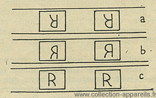 Consider, on the support side, i.e., in the position it occupied in the camera, a stereoscopic image, for example, in color. The images appear as if each of them has rotated 180° within its plane, around its center, compared to the normal orientation of the subject. For example, if we have photographed the letter "R," it will appear as shown in figure 5a.
To restore the normal orientation, two optical reflections are required: one that swaps the top and bottom (resulting in 5b), and another that swaps the left and right of each image (resulting in 5c). These two reflections can be obtained simultaneously in a roof prism with the edge of the dihedral angle inclined at 45° to the line of sight. However, this requires placing the film in a plane parallel to the line of sight and no longer perpendicular, as it is in a regular stereoscope. This is why we have positioned the film on the top rather than the back of the stereoscope.
Although unconventional, this arrangement seemed at least as rational as the classical one because light, whether coming from the sky or a lamp, more often arrives from above than from the front.
The only significant drawback of the prism-based design is its high production cost. Unfortunately, the use of mirrors, initially attractive due to its cost-effectiveness, had to be irrevocably rejected due to the inevitable double reflections.
In short, these are the main considerations that guided the development of the Vérascope 40 and its accessories. We have presented them honestly, without claiming that they have absolute or definitive value because, in the realm of photography, as in any other field, nothing is (fortunately) set in stone.
Interesting links or bibliography :
Add a link or element of bibliography, a picture taken with this camera, a picture of box or an ads about this camera
Your photos taken with the same camera:
Cameras from Ebay France (Richard Jules) (Uploaded each 3 hours)